
Why does the desurveying method for drillholes matter?
Drillholes are often oriented towards a specific target (azimuth and plunge) but the drill bit often deviates unintentionally due to individual drilling techniques and/or rock hardness anisotropy. To monitor progress of each hole with respect to a set trajectory, it is necessary to undertake down-the-hole directional surveys to measure azimuth and plunge. Some surveying instruments can take continuous downhole measurements. But more typically, measurements are made at specific depths.
The locations of the survey points are known only from their downhole distance, which becomes increasingly important with targets at greater depths below surface. Interpretation of the drillhole path from discontinuous downhole measurements is known as desurveying where the true shape of the drillhole trace between survey points is unknown.
There are a number of different desurveying methods, each making assumptions about the borehole path, e.g. straight line segments, sudden orientation changes, etc. A number of methods implemented by geological and resource modelling packages include: tangential, balanced tangential, spherical arcs (or minimum curvature), average angle, radius of curvature, etc. But does it matter which method is used?
Often the desurvey method option is limited by the software of choice. This can create several problems. For example, the geologist may use one software solution to model surfaces (e.g. base of total oxidation) and solids (e.g. mineral domains), and the resource geologist uses another solution for Mineral Resource estimation.
This technical article explores the ramifications for using different desurvey methods during a typical mineral resource estimate workflow, i.e. from 1) geological modelling (e.g. snapping to drillhole intercepts), to 2) mineral resource estimation.
Background
Many styles of mineralisation are explored by drilling vertical holes, for example, nickel laterite, alumina bauxite, disseminated porphyrys, etc. However, with more complex metals and mineralisation styles the geometries are less straightforward and structural controls play an important role for modelling the shape of the orebody. For these scenarios, drillholes are normally oriented orthogonal to the predicted geometry of the mineralisation in order to get a representative sample (e.g. true thickness). Where the hole is perfectly orientated perpendicular to the mineralised body at 90º, the intersection of mineralisation represents the true thickness of the body. While this is not always achievable due to the very nature of exploring for hidden mineralisation, drillholes will be constantly updated for direction and plunge as new information is modelled from drillhole measurements.
Desurvey methods
Desurveying is the process of determining the position (3-dimensional coordinate) down a drillhole given the collar location and downhole survey data. It is common practice to survey a hole to obtain known values of dip and dip direction at regular downhole distances along the hole’s length. From collar location and survey measurements the actual coordinates along the hole are then calculated.
Below, three of the most common desurvey methods are considered, namely 1) Tangential, 2) Balanced Tangential, and 3) Spherical Arcs.
Tangential
The most straightforward desurvey method is Tangential. It assumes that changes in plunge and azimuth occur instantly at the end of the survey interval, treating the preceding interval as a straight line that uses the previous survey’s plunge and azimuth (i.e. dip direction). The hole is considered to travel in a straight line between survey stations. For each interval, the depth, plunge, and azimuth at the end of the interval are used to calculate the location in three-dimensions (3D), beginning with the collar position and then at increments based on frequency of downhole survey measurements.
This method has the advantage of being simple and fast to compute and was historically common and widely used. The disadvantages are that it is much less accurate than other methods especially for longer intervals or rapidly changing hole orientations. Also, the assumption of abrupt changes in hole trajectory is physically unrealistic.
Balanced Tangential
The Balanced Tangential Method is an improvement over the basic Tangential method, providing a more realistic geometry while maintaining relatively simple calculations. It assumes that the change in plunge and azimuth happens gradually over the survey interval and not just at the end, by averaging the angles at the start and end of each segment.
The trajectory between two survey points is assumed to be straight. The average plunge and azimuth between the start and end of the intervals are used to calculate the displacement. The coordinates in 3D space are updated incrementally from the collar using trigonometric calculations based on the averaged angles.
It has the advantage of being more realistic than the Tangential method, especially for moderate curvature. The calculations are computationally simple and it provides a better approximation of the actual hole trajectory. However, it still assumes a straight-line path between survey points (not a true curve), which can introduce errors particularly where there are high-deviations in plunge and azimuth, and long downhole intervals between measurements.
Spherical Arcs
The Spherical Arcs Method (also known as minimum curvature) is a technique used to model the path of a drillhole by assuming that the trajectory between two survey stations follows a curved path on the surface of a sphere. It is a mathematically robust alternative to simple linear approximations.
This method assumes that the plunge and azimuth change smoothly and continuously along the arc of a sphere between two points, rather than in straight lines or sudden changes. The hole trajectory is treated as a segment of a great circle (the shortest path on a sphere's surface), with directional changes distributed evenly along the arc.
For each interval between two survey points, the method uses the start and end plunge and azimuth to define the arc’s curvature. The 3D coordinate is calculated based on the arc’s orientation and length. The displacements along the hole’s path begins with the known collar location and its plunge and azimuth and are summed to reconstruct the trajectory.
This method is one of the most accurate, especially in holes with significant deviation or curvature. It represents the actual path of the drillhole more smoothly and realistically than straight-line methods.
Summary
The simplest method for drillhole desurveying is Tangential but it is also the least accurate. The most realistic is Spherical Arcs but it is more complex to compute. For short holes, or with holes that have frequent downhole surveys, the basic tangential method is acceptable, but for longer holes, where deviations are common, and/or there are long survey intervals between downhole measurements, the most accurate technique is Spherical Arcs.
Figure 1 summaries the assumptions that each method uses and the resulting geometry or trajectory of the path.
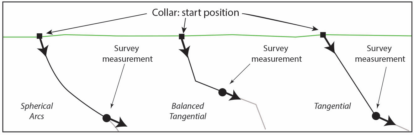
Figure 1: Drillhole survey plots
Table 1 gives a short summary of each method, the assumptions made on the hole’s trajectory, the use of downhole dip and dip direction, the level accuracy, the advantages and disadvantages of each, and where each is best used. A visual comparison is provided in Figure 2.
Table 1: Summary comparisons between different methods
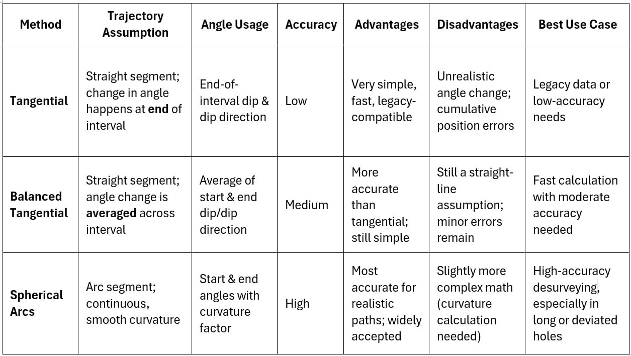
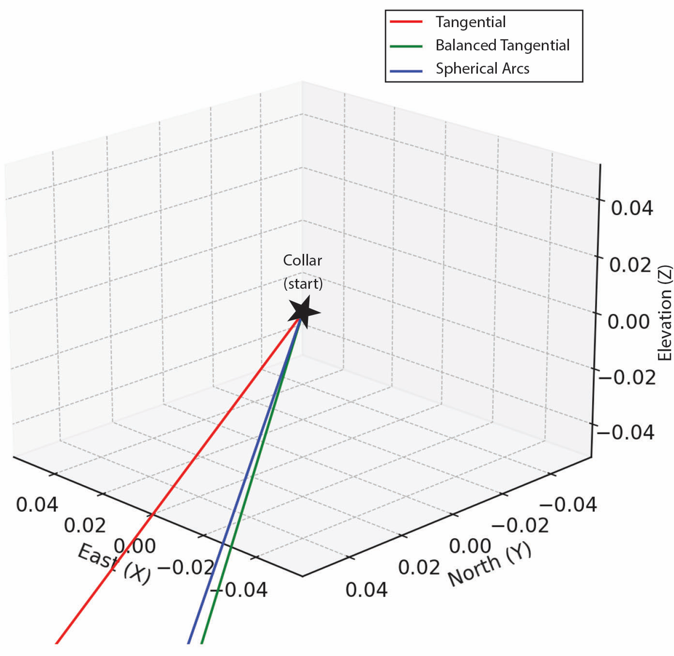
Figure 2: Visual comparison of each desurvey method. Units are coordinates showing drillhole trace.
Implications
It is clear that different desurvey methods produce different results for the location down the hole at any given distance from the collar within a drillhole. Often the method used is not given much thought, and the default desurvey method implemented by the software of choice is used.
Drillhole data will often be imported into a 3D modelling geological package using the default desurvey method of the software. At this stage, after validation and fixing of any errors in the drillhole tables (e.g. overlapping intervals) interpretation of surfaces such as base of complete oxidation, modelling of geological domains, grade shells, etc will be completed. This can be implicitly driven by the software or explicit where the interpreter may create a number of vertical 2D sections and then use polylines to correlate and snap to the drillhole intersection, which are then subsequently linked up to form 3D volumes from 2D sections.
When the domains and surfaces are then provided to the resource geologist for mineral resource estimation, these will be imported and used to flag the drillholes. It may be fortuitous or through good communication between the geologist (modeller) and resource geologist (Competent Person) that the same desurvey method is used between different software. But if not, then consequently the domains and surfaces will not be in the same position in relation to the drillholes. This will then be compounded by compositing the samples / assays to domain boundaries which is often commonly done. It can result in several high-grade samples being omitted and low grade or waste being incorporated into the estimate. Where the mineral resource is marginal in terms of meeting the “reasonable prospects of eventual economic extraction”, it can kill the project.
Hence, it is critical that the geologist and the resource geologist communicate about which desurvey method both should use from the beginning of the project.
Please note: Bulletin articles are general in nature and not peer reviewed.