
Strategic short-term geotechnical design
This article is an edited excerpt of a paper presented at AusIMM’s Open Pit Operators Conference in 2022.
The principal objective of geotechnical engineers supporting operating mines is to provide safe working conditions and ensure that pit designs are geotechnically optimised to site conditions and pre-defined stability requirements.
With optimised slope configuration parameters that satisfy respective safety factors for the project stage, geotechnical designs are developed and approved as official mine plan design before the final design geometry is implemented in the field.
However, due to unforeseen factors or circumstances that can affect the mining production cycle, production needs result in a plan that does not adhere to the standard pit design protocols or, in some cases, a long-term strategic plan. In these instances, geotechnical engineers must assess the individual factors and deliver advice that satisfies the following:
- facilitates the short-term production demands of the mine
- maintains a safe operational environment
- does not overly compromise the long-term strategic requirements of the mine plan.
Combining the above factors means that non-conventional designs that mitigate the developed situations are required. Design options not commonly available to the geotechnical engineer may be required. These designs often affect production times and deliverables, requiring various options to solve the problem in the safest and shortest period. The result is that the designs are bespoke, require a detailed understanding of the failure mode and mechanism and a dynamic approach to managing the risk as the slope is excavated. These non-standard designs are short-term strategic geotechnical designs.
Strategic short-term geotechnical design
Strategic short-term geotechnical design is a process of creating pit designs that satisfy a short-term strategic requirement. This requirement may be to address:
- a latent geotechnical hazard that impacts pit slope stability
- a known geotechnical risk that creates a hazardous working environment for both people and equipment
- an opportunity to improve reserve recovery
- commodities market changes (positive or negative)
- short-term production needs
- maximising resource recovery for the final void or final ‘good-bye’ cuts when the pit reaches its final design limits
- an improved understanding of rock mass conditions and design assumptions, accommodating a more aggressive design for the final benches.
As the problem to be addressed is a short-term issue, geotechnical engineers often provide bespoke short-term designs that deviate from the more conservative long-term design geometry. Strategic short-term designs are typically more aggressive and may not satisfy all design criteria guidelines adopted for mid- or long-term pit design. Therefore, the geotechnical engineer must ensure the working environment safety requirement to ensure the safety of people and the equipment of all workers while following a robust design process (Figure 1) all of the mine’s needs are satisfied. An overview of this process is outlined below.
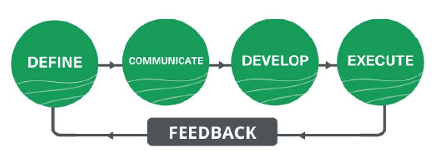
Figure 1. Design process for short-term geotechnical design.
Define
The Definition phase of the process is required to define the intent of design change, often resulting from an observed hazard in the sequence of mining or after a failure event that restricts recovery of reserve ore. The design change is often strategised around the imminent failure or post-failure event, leading to subsequent development of a new plan that circumvents the risk posed by the failure (post-event) or impending failure.
Develop
Once a pit slope design has been implemented, the Geotechnical Engineer has limited options to develop a hazard mitigation design. The Geotechnical Engineer should engage and liaise with other departments, ie Geology and Mine Planning to ensure confidence in the design inputs and assumptions. Additionally, Production Superintendents should also be engaged to ensure that the design being developed by the Geotechnical Engineer is practical, and Production crews are comfortable executing it.
Communicate
Communication of the plan to all key stakeholders is required to ensure everyone is on board. As Geotechnical Engineers are rarely the people operating directly in the line of fire, it is vital to ensure the plan and justification for the plan is clearly communicated and all concerns addressed. It is crucial to have all personnel buy into the plan and understand the importance of all their observations during mining.
Execute
Upon acceptance of the design by all stakeholders, the strategy and plan need to be executed. Mining is adept at implementing the Observational Method. Due to the natural heterogeneity and variability of rock masses, a geotechnical practitioner cannot develop a model that is 100 per cent accurate due to the inherent uncertainty associated with respective input parameters. Therefore, the Observational Method is employed to manage the risk during execution. For more detail, Eurocode 7 (EN 1997–1:2004; CEN, 2004) outlines the approach to be taken and the parameters that must be developed during the ‘Development’ phase.
Feedback
Like all good design processes, the design’s performance should be recorded and measured for future reference. Where required, this information should be fed back into the next design to optimise its performance and safety.
Where possible, data that should be recorded for future reference include:
- deformation rates
- slope (geological structure) behaviour
- size of the instability
- run-out distance
- failure volume.
Case study
Site A – slope buttressing
Site background
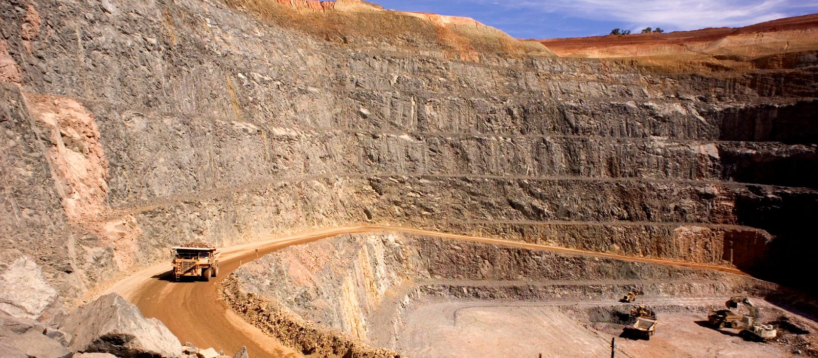
Site A is located in south-east Queensland, and the mine has been in operation for over 20 years. The site has been through multiple ownerships that have considered different design approaches and several iterations of slope angles. The site is a single-pit source, utilising conventional drill and blast and load and haul mining methods.
Slope geometry was varied through different ownerships from 5 m bench heights and 5 m berm width to the current configuration 30 m bench height and 15 m berm width. The current bench height is mined through a double bench system, where two blasting episodes are conducted on each 15 m interval (mid-bench) for each production block sequentially. These blasted blocks are then split into two mining flitches each 7.5 m to suit the site’s mining equipment.
The open pit is situated within a complex geological and structural suite with variable rock mass quality. These complex structural networks within the deposit are associated with multiple complex slope failure modes with wedge and planar failures dominating the geotechnical domains (CEN, 2004).
Site geology and hydrogeology
The host rock for Site A comprises mostly dacitic rocks within a clastic rocks package with a robust volcanic association. The sequence of the volcanic rocks varies entirely from sedimentary to magmatic. A literature review of the site shows that the host rocks are clast supported volcaniclastic rock probably derived from an eruption and deposited proximal to the vent. The site has undergone various alteration episodes with a dominant sericite alteration on the open pit’s Western slope. This alteration has been associated with the emplacement of the mineralised dacitic dome.
The alteration compounded by the complex structural networks, which are primarily low-angled (30–45°), has been a significant instigator in the ground challenges experienced on the west wall of Site A.
The groundwater at Site A is mostly compartmentalised due to the fractured rock system and low matrix permeability. Aquifer storage and hydraulic diffusivity are also low, implying that the groundwater in the current pit shell’s vicinity is exceptionally high and exhibits a steep cone of depression.
1. Problem definition
Site A has had ground challenges and slope management challenges throughout its life. These challenges include rockfalls, bench-scale to multiple bench slope failures. A brief description of how a slope failure was managing through the implementation of effective short-term planning is discussed below.
West Wall Failure
A failure was picked by the deployed two ground-based interferometric synthetic aperture radars (GB-InSAR). The block displacement was controlled by a steep basal plane and two subvertical planes, shown in Figures 2 and 3 respectively.
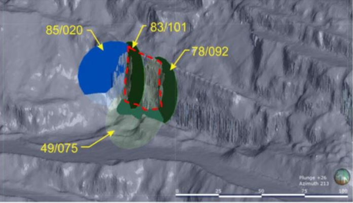
Figure 2. 3D model showing the as-built pit shell with the mapped joint planes defining the block (red dotted line).
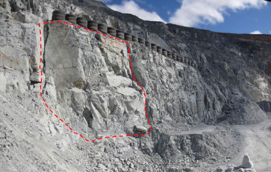
Figure 3. Photo showing the block and the controlling structures.
The failure occurred during the final pit shell excavation, and it required an immediate change in short-term mining plans to manage the failure and re-direct production to other areas to continue production cycles.
2. Development of strategy (short-term plan inception)
Some strategies that were adopted to manage the geotechnical risks included:
- detailed mapping of the structural networks
- implementation of trigger action response plans (TARPS) when working proximal to the pit highwalls
- slope monitoring through radars – with two radars installed for full-pit monitoring.
- installation of robust instrumentation – time-domain reflectometers (TDRs), nested piezometers
- remote drilling in high-risk areas
- an integrated risk management framework that incorporates all the strategies.
Monitoring radar information recorded that the inception of the failure was when the last flitch’s excavation was begun.
Short-term plans had to be changed to meet ore deliverables for the plant. The initial plan was to re-design the interim pit shell at the pit bottom and open up benches that would accommodate the production target until remediation of the failure area was completed, which would allow mining to continue on the final pit shell design.
Failure remediation was done by buttressing the failure block by waste rock mined from the pit bottom and the south cutback. Buttressing was done by a remote-operated dozer with dump trucks dumping short on the tip end and the dozer pushing the material to wrap around the failure area.
3. Communication of plan
All mining crews were notified of the change in plan and mining sequences. Four sessions were conducted through meetings to cover all four working shifts for both day and night shifts. A presentation was conducted and disseminated to the whole site alerting all mine personnel of the hazard and the changes to the mine plan.
4. Execution of plan
The short plan to manage the failure was executed as per the plan with a remote dozer involved with the emplacement of the waste rock at the toe of the failure to stabilise the failure and built up the ramp to 0 mRL. This process was conducted through haul trucks short-dumping waste material from the bottom of the pit and the remote dozer pushing the material against the wall to mobilise a buttressing effect onto the creeping block.
5. Feedback
Feedback on the process was done during the implementation process and post-implementation. The feedback process allowed all the people to be updated on the progress of the remediation process and track the progress of the remediation process against the scheduled time for the remedial works. Considering that this process was critical in re-establishing the long-term mine and getting back on track to open up the pit to the final design wall to access the bottom ore, higher ore grades were anticipated.
Readers can purchase and download the full paper, which includes more detail and an additional case study, as part of the Open Pit Operators 2022 Conference Proceedings here.
Reference
CEN, 2004. EN 1997–1:2004, Eurocode 7: Geotechnical design – Part 1: General rules, Brussels: European Committee for Standardisation.